ISAC (Isotope Separator and ACcelerator): Difference between revisions
| Line 106: | Line 106: | ||
| | | | ||
==== Table 1 | ==== Table 1 ==== | ||
{| style="color:black;background-color:#D0DEE1;" cellpadding="5" cellspacing="0" border="1" | {| style="color:black;background-color:#D0DEE1;" cellpadding="5" cellspacing="0" border="1" | ||
|+ style="font-size:110%; font-weight:bold;" | | |+ style="font-size:110%; font-weight:bold;" | | ||
Revision as of 18:40, 23 November 2007
ISAC beam intensities
|
A list of representative radioactive ion beam yields (PDF, 100 KB) available at ISAC has been prepared by the ISAC Radioactive Ion Beam Development group. |
About the accelerators ...
|
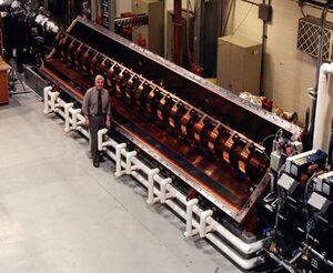
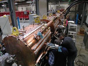
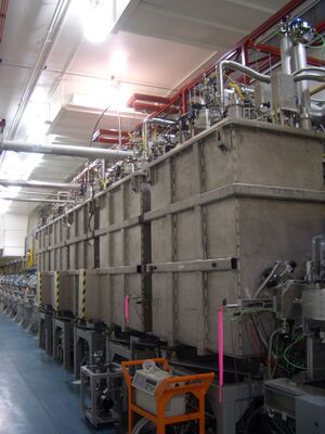
In the ISAC facility we accelerate both radioactive beam produced by the ISAC target stations and stable beam from an off line ion source (OLIS). The first stage of acceleration in ISAC I happens in the RFQ (radio frequency quadrupole). By design an RFQ has a well defined velocity profile where the final velocity is independent from the accelerated ion. ISAC RFQ is designed to accelerate particles of mass to charge ratio up to 30 from an energy of 2 keV/u to 150 keV/u. In order to improve the beam quality and transmission we bunch the beam injected into the RFQ by means of a prebuncher. The beam is bunched at the third sub harmonic of the RFQ resonant frequency of 35.36 MHz. Bunching at 11.78 MHz means that the time structure after the RFQ is characterized by a main bunch and two small satellites separated each other by 28.3 ns. An 11 Mhz chopper located downstream of the RFQ can kick out of axis the two satellites cleaning the time structure so that only main bunches are present and separated by 84.8 ns. Furthermore the separation between main bunches can be increased from 84.8 ns to 169.7 ns using a second 5 MHz chopper (in this case though half of the beam is lost). The RFQ can be also run without the prebuncher obtaining a time structure of equal populated bunches. Nevertheless this running mode lowers the RFQ transmission from 75% to 25% (see Table 1, below). After the RFQ the beam charge state is increased by means of a carbon stripping foil and then bunched in time before entering the downstream linac. The efficiency of the stripping depends on the accelerated ions, in general it varies between 30-50%. The second stage of acceleration is accomplished with a drift tube linac (DTL). A DTL is a more flexible machine where the final energy varies within a certain range of energies, depending on the machine design. ISAC DTL operating at 106.08 MHz is divided into eight modules (five accelerating structures and three bunchers) that allow great flexibility on the final energies we can tune. The beam is “rebunched” in time at the DTL entrance by means of the MEBT rebuncher. The DTL accepts ions with mass to charge ratio between 2 and 6 and, depending on the ratio, it accelerates them from 150 keV/u to 1.9 MeV/u (Table 2). The DTL transmits more than 85% of the incoming beam. The beam delivered to the ISAC I experimental stations can be further bunched in time from 4 ns to 1 ns, or in energy from 0.4% to less than 0.1%, by means of a buncher located downstream the DTL; in any case the longitudinal estimated emittance is 1.5 π keV/u ns. For example since the longitudinal emittance is the area of an ellipse in the longitudinal phase space (ns,keV/u) this means that for a bunch of 1 ns full width the energy spread is 6 keV/u. The new ISAC II superconducting linac (SCLINAC) can be considered the third acceleration stage of the ISAC facility. The ion beam at 1.5 MeV/u coming from the DTL is injected into the ISAC II linac. The linac is composed of twenty superconducting quarter wave (QWR) cavities distributed in five cryomodules. Each cavity is independently phased and typically run, but not necessarily, at a maximum voltage of ~1 MV. The total of the cavities can increase the voltage by 20 MV. This design provide great flexibility allowing any energy between 1.5 MeV/u and 10.5 MeV/u in case of ion with mass to charge ratio of 2 (Table 3). By license though we are currently limited to deliver a maximum energy of 5 MeV/u. The superconducting linac serves experimental stations (some of them still under construction) located in the ISAC II experimental hall. In the future a superconducting buncher will be installed downstream of the superconducting linac in order to bunch the beam in time or energy at the ISAC II experimental station. At the present for beam energies requiring only a subset of cavities on, the last cavity in the linac can be used to reduce the energy spread. For both ISAC I and ISAC II experimental stations the standard final spot is usually 2 mm wide, but dedicated optics solutions can be arranged in order to accommodate experiment requests. The measured normalized transverse emittance is 0.2π mm mrad. The beam characteristics are summarized in Table 4. |
ISAC accelerator specifications
Table 1
Table 2: ISAC-I energies
Table 3: ISAC-II energies
Please note that the maximum beam energy is currently limited by TRIUMF's operating license to 5 MeV/u.
Table 4: Beam characteristics
|


